


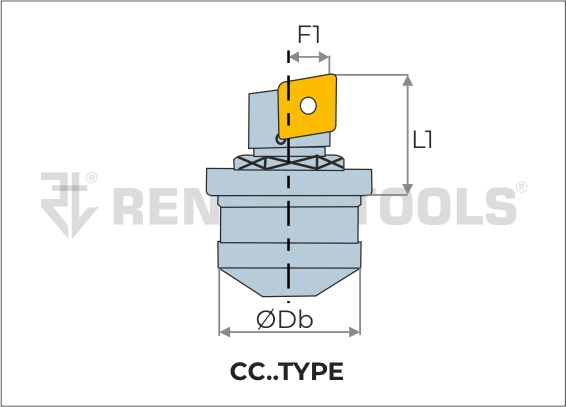
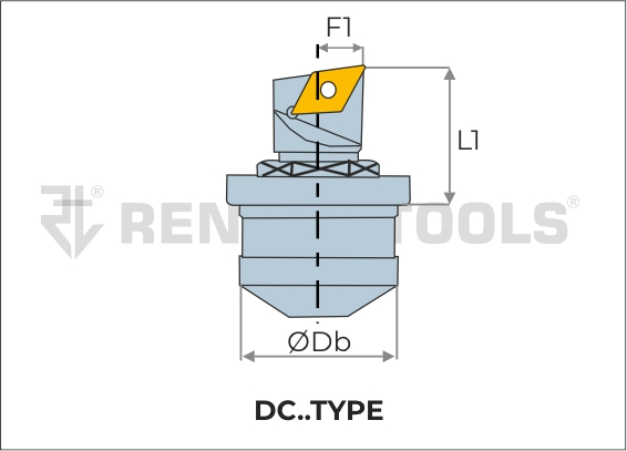
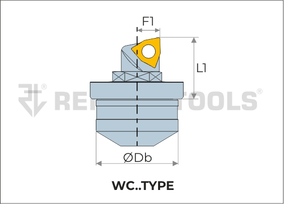
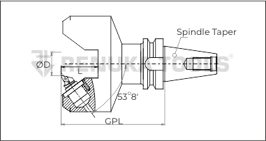
| Sr. No | Item Code | Insert | Db | L1 | F1 | Dmin | Mounting
Screw |
Insert
Screw |
Torx | Spanner | |
|---|---|---|---|---|---|---|---|---|---|---|---|
| LH | RH | ||||||||||
| 1 | RT MBU ALW 02 14 | RT MBU ARW 02 14 | WC..0201.. | 14 | 11.50 | 1.00 | 20.00 | RTMS14 | M2.0 | T6/T8 | RTS14 |
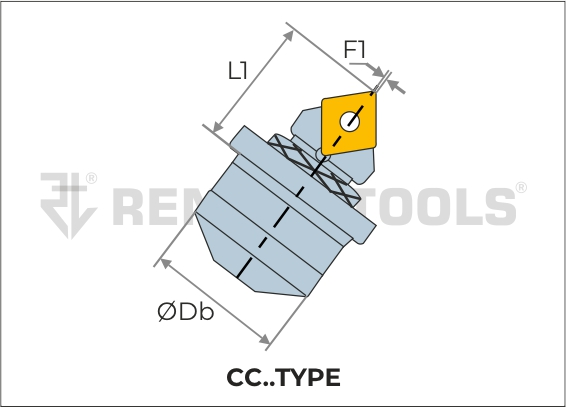
| 2 | RT MBU ALC 04 14 | RT MBU ARC 04 14 | CC..04T0.. | 14 | 11.50 | 1.00 | 20.00 | RTMS14 | M2.0 | T6/T8 | RTS14 |
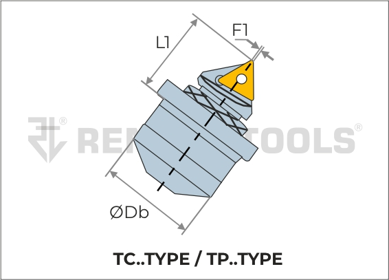
| 3 | RT MBU ALT 06T1 14 | RT MBU ART 06T1 14 | TC..06T1.. | 14 | 11.50 | 0.20 | 20.00 | RTMS14 | M2.0 | T6/T8 | RTS14 |
| 4 | RT MBU ALT 0601 14 | RT MBU ART 0601 14 | TC..0601.. | 14 | 11.50 | 0.20 | 20.00 | RTMS14 | M2.0 | T6/T8 | RTS14 |
| 5 | RT MBU ALC 06 16 | RT MBU ARC 06 16 | CC..0602.. | 16 | 14.30 | 0.45 | 25.90 | RTMS16 | M2.5 | T8/T10 | RTS16 |
| 6 | RT MBU ALT 06T1 16 | RT MBU ART 06T1 16 | TC..06T1.. | 16 | 14.30 | 0.20 | 25.40 | RTMS16 | M2.0 | T6/T10 | RTS16 |
| 7 | RT MBU ALT 0601 16 | RT MBU ART 0601 16 | TC..0601.. | 16 | 14.30 | 0.20 | 25.40 | RTMS16 | M2.0 | T6/T10 | RTS16 |
| 8 | RT MBU ALC 09 20 | RT MBU ARC 09 20 | CC..09T3.. | 20 | 19.10 | 1.00 | 33.10 | RTMS20 | M3.5 | T15/T10 | RTS20 |
| 9 | RT MBU ALT 09 20 | RT MBU ART 09 20 | TC..0902.. | 20 | 19.10 | 1.00 | 33.10 | RTMS20 | M2.2 | T7/T10 | RTS20 |
| 10 | RT MBU ALTP 09 20 | RT MBU ARTP 09 20 | TP..0902.. | 20 | 19.10 | 1.00 | 33.10 | RTMS20 | M2.5 | T8/T10 | RTS20 |
| 11 | RT MBU ALD 07 20 | RT MBU ARD 07 20 | DC..0702.. | 20 | 19.10 | 1.00 | 33.10 | RTMS20 | M2.5 | T8/T10 | RTS20 |
| 12 | RT MBU ALC 09 22 | RT MBU ARC 09 22 | CC..09T3.. | 22 | 23.00 | 1.10 | 42.60 | RTMS22 | M3.5 | T15 | RTS22 |
| 13 | RT MBU ALT 1102 22 | RT MBU ART 1102 22 | TC..1102.. | 22 | 23.00 | 1.10 | 42.60 | RTMS22 | M2.5 | T8/T15 | RTS22 |
| 14 | RT MBU ALT 1103 22 | RT MBU ART 1103 22 | TC..1103.. | 22 | 23.00 | 1.10 | 42.60 | RTMS22 | M2.5 | T8/T15 | RTS22 |
| 15 | RT MBU ALTP 11 22 | RT MBU ARTP 11 22 | TP..1103.. | 22 | 23.00 | 1.10 | 42.60 | RTMS22 | M3.0 | T10/T15 | RTS22 |
| 16 | RT MBU ALD 07 22 | RT MBU ARD 07 22 | DC..0702.. | 22 | 25.00 | 2.30 | 42.60 | RTMS22 | M2.5 | T8/T15 | RTS22 |
| 17 | RT MBU ALC 12 32 | RT MBU ARC 12 32 | CC..1204.. | 32 | 33.30 | 1.00 | 60.60 | RTMS32 | M4.5 | T20/3MM | RTS32 |
| 18 | RT MBU ALT 16 32 | RT MBU ART 16 32 | TC..16T3.. | 32 | 33.30 | 1.20 | 60.60 | RTMS32 | M3.5 | T15/3MM | RTS32 |
| 19 | RT MBU ALTP 16T3 32 | RT MBU ARTP 16T3 32 | TP..16T3.. | 32 | 33.30 | 1.20 | 60.60 | RTMS32 | M3.5 | T15/3MM | RTS32 |
| 20 | RT MBU ALTP 1604 32 | RT MBU ARTP 1604 32 | TP..1604.. | 32 | 33.30 | 1.20 | 60.60 | RTMS32 | M4.0 | T15/3MM | RTS32 |


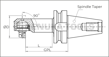
| Sr. No | Item Code | Insert | Db | L1 | F1 | Dmin | Mounting
Screw |
Insert
Screw |
Torx | Spanner | |
|---|---|---|---|---|---|---|---|---|---|---|---|
| LH | RH | ||||||||||
|
1 |
RT MBU SLW 02 14 |
RT MBU SRW 02 14 |
WC..0201.. |
14 |
11.0 |
4.1 |
22.0 |
RTMS14 |
M2.0 |
T6/T8 |
RTS14 |
|
2 |
RT MBU SLC 04 14 |
RT MBU SRC 04 14 |
CC..04T0.. |
14 |
11.0 |
4.1 |
22.0 |
RTMS14 |
M2.0 |
T6/T8 |
RTS14 |
|
3 |
RT MBU SLT 06T1 14 |
RT MBU SRT 06T1 14 |
TC..06T1.. |
14 |
11.0 |
4.1 |
22.0 |
RTMS14 |
M2.0 |
T6/T8 |
RTS14 |
|
4 |
RT MBU SLT 0601 14 |
RT MBU SRT 0601 14 |
TC..0601.. |
14 |
11.0 |
4.1 |
22.0 |
RTMS14 |
M2.0 |
T6/T8 |
RTS14 |
|
5 |
RT MBU SLC 06 16 |
RT MBU SRC 06 16 |
CC..0602.. |
16 |
13.3 |
5.1 |
27.6 |
RTMS16 |
M2.5 |
T8/T10 |
RTS16 |
|
6 |
RT MBU SLT 06T1 16 |
RT MBU SRT 06T1 16 |
TC..06T1.. |
16 |
13.3 |
4.1 |
27.1 |
RTMS16 |
M2.0 |
T6/T10 |
RTS16 |
|
7 |
RT MBU SLT 0601 16 |
RT MBU SRT 0601 16 |
TC..0601.. |
16 |
13.3 |
4.1 |
27.1 |
RTMS16 |
M2.0 |
T6/T10 |
RTS16 |
|
8 |
RT MBU SLC 09 20 |
RT MBU SRC 09 20 |
CC..09T3.. |
20 |
18.3 |
7.2 |
37.1 |
RTMS20 |
M3.5 |
T15/T10 |
RTS20 |
|
9 |
RT MBU SLT 09 20 |
RT MBU SRT 09 20 |
TC..0902.. |
20 |
18.3 |
6.3 |
37.1 |
RTMS20 |
M2.2 |
T7/T10 |
RTS20 |
|
10 |
RT MBU SLTP 09 20 |
RT MBU SRTP 09 20 |
TP..0902.. |
20 |
18.3 |
6.3 |
37.1 |
RTMS20 |
M2.5 |
T8/T10 |
RTS20 |
|
11 |
RT MBU SLD 07 20 |
RT MBU SRD 07 20 |
DC..0702.. |
20 |
18.3 |
6.3 |
37.1 |
RTMS20 |
M2.5 |
T8/T10 |
RTS20 |
|
12 |
RT MBU SLC 09 22 |
RT MBU SRC 09 22 |
CC..09T3.. |
22 |
22.1 |
7.2 |
49.1 |
RTMS22 |
M3.5 |
T15 |
RTS22 |
|
13 |
RT MBU SLT 1102 22 |
RT MBU SRT 1102 22 |
TC..1102.. |
22 |
22.1 |
7.2 |
49.1 |
RTMS22 |
M2.5 |
T8/T15 |
RTS22 |
|
14 |
RT MBU SLT 1103 22 |
RT MBU SRT 1103 22 |
TC..1103.. |
22 |
22.1 |
7.2 |
49.1 |
RTMS22 |
M2.5 |
T8/T15 |
RTS22 |
|
15 |
RT MBU SLTP 11 22 |
RT MBU SRTP 11 22 |
TP..1103.. |
22 |
22.1 |
7.2 |
49.1 |
RTMS22 |
M3.0 |
T10/T15 |
RTS22 |
|
16 |
RT MBU SLD 07 22 |
RT MBU SRD 07 22 |
DC..0702.. |
22 |
22.1 |
7.2 |
49.1 |
RTMS22 |
M2.5 |
T8/T15 |
RTS22 |
|
17 |
RT MBU SLC 12 32 |
RT MBU SRC 12 32 |
CC..1204.. |
32 |
32 |
10.3 |
69.6 |
RTMS32 |
M4.5 |
T20/3MM |
RTS32 |
|
18 |
RT MBU SLT 16 32 |
RT MBU SRT 16 32 |
TC..16T3.. |
32 |
32 |
10.3 |
69.6 |
RTMS32 |
M3.5 |
T15/3MM |
RTS32 |
|
19 |
RT MBU SLTP 16T3 32 |
RT MBU SRTP 16T3 32 |
TP..16T3.. |
32 |
32 |
10.3 |
69.6 |
RTMS32 |
M3.5 |
T15/3MM |
RTS32 |
|
20 |
RT MBU SLTP 1604 32 |
RT MBU SRTP 1604 32 |
TP..1604.. |
32 |
32 |
10.3 |
69.6 |
RTMS32 |
M4.0 |
T15/3MM |
RTS32 |


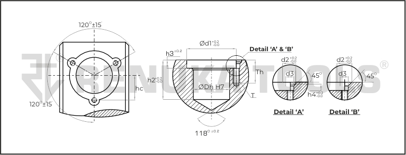
| Detail | Sr.No. | DbH7 | d1 | d2 | d3 | h3 | h4 | h5 | Th | hc | T |
|---|---|---|---|---|---|---|---|---|---|---|---|
|
A |
1 |
14.0 |
16.0 |
3.7 |
2.7 |
9.3 |
2.8 |
1.2 |
8.0 |
8.65 ±0.02 |
M2.5 |
|
2 |
16.0 |
19.0 |
4.6 |
3.2 |
11.5 |
2.8 |
1.6 |
9.0 |
9.65 ±0.02 |
M3.0 |
|
|
3 |
20.0 |
25.0 |
4.6 |
3.2 |
15.5 |
4.0 |
1.6 |
9.0 |
12.50 ±0.05 |
M3.0 |
|
|
4 |
22.0 |
30.0 |
6.5 |
4.3 |
24.0 |
5.0 |
1.8 |
13.0 |
15.40 ±0.05 |
M4.0 |
|
|
B |
5 |
32.0 |
46.0 |
11.9 |
5.4 |
33.0 |
6.3 |
- |
16.0 |
23.00 ±0.05 |
M5.0 |

| sr no | Db | RT MBU ITEM CODE | INSERTS | D min | D2 | Bmin | h1max | Smin | S1mean | -ve range (radial) | +ve range (radial) | |
|---|---|---|---|---|---|---|---|---|---|---|---|---|
| LH | RH | |||||||||||
| 1 | 14 | ALW 02 14 | ARW 02 14 | WC..020104 | 20 | 19 | 0.4 | 1.5 | 8.3 | 8.425 | 0.1 | 1.4 |
| 2 | 14 | ALT 06T1 14 | ART 06T1 14 | TC..06T104 | 20 | 19 | 0.4 | 1.5 | 8.3 | 8.425 | 0.1 | 1.4 |
| 3 | 14 | ALT 0601 14 | ART 0601 14 | TC..060104 | 20 | 19 | 0.4 | 1.5 | 8.3 | 8.425 | 0.1 | 1.4 |
| 4 | 14 | ALC 04 14 | ARC 04 14 | CC..04T004 | 20 | 19 | 0.4 | 1.5 | 8.3 | 8.425 | 0.1 | 1.4 |
| 5 | 16 | ALC 06 16 | ARC 06 16 | CC..060204 | 25.9 | 23 | 1.05 | 2 | 10.7 | 11.2 | 0.4 | 1.6 |
| 6 | 16 | ALT 06T1 16 | ART 06T1 16 | TC..06T104 | 25.4 | 23 | 0.8 | 2 | 10.6 | 11.1 | 0.4 | 1.6 |
| 7 | 16 | ALT 0601 16 | ART 0601 16 | TC..060104 | 25.4 | 23 | 0.8 | 2 | 10.6 | 11.1 | 0.4 | 1.6 |
| 8 | 20 | ALC 09 20 | ARC 09 20 | CC..09T304 | 33.1 | 30 | 0.95 | 2.8 | 14.5 | 15.25 | 0.6 | 2.2 |
| 9 | 20 | ALT 09 20 | ART 09 20 | TC..090204 | 33.1 | 30 | 0.95 | 2.8 | 14.5 | 15.25 | 0.6 | 2.2 |
| 10 | 20 | ALTP 09 20 | ARTP 09 20 | TP..090204 | 33.1 | 30 | 0.95 | 2.8 | 14.5 | 15.25 | 0.6 | 2.2 |
| 11 | 20 | ALD 09 20 | ARD 09 20 | DC..070204 | 33.1 | 30 | 0.95 | 2.8 | 14.5 | 15.25 | 0.6 | 2.2 |
| 12 | 22 | ALC 09 22 | ARC 09 22 | CC..09T304 | 42.6 | 39.6 | 0.9 | 4.8 | 17.2 | 17.95 | 0.6 | 4.2 |
| 13 | 22 | ALT 1102 22 | ART 1102 22 | TC..110204 | 42.6 | 39.6 | 0.9 | 4.8 | 17.2 | 17.95 | 0.6 | 4.2 |
| 14 | 22 | ALT 1103 22 | ART 1103 22 | TC..110304 | 42.6 | 39.6 | 0.9 | 4.8 | 17.2 | 17.95 | 0.6 | 4.2 |
| 15 | 22 | ALTP 11 22 | ARTP 11 22 | TP..110304 | 42.6 | 39.6 | 0.9 | 4.8 | 17.2 | 17.95 | 0.6 | 4.2 |
| 16 | 22 | ALD 11 22 | ARD 11 22 | DC..070204 | 42.6 | 39.6 | 0.9 | 4.8 | 17.2 | 17.95 | 0.6 | 4.2 |
| 17 | 32 | ALC 12 32 | ARC 12 32 | CC..120404 | 60.6 | 56.6 | 1.4 | 8 | 26.2 | 26.95 | 0.6 | 7.4 |
| 18 | 32 | ALT 16 32 | ART 16 32 | TC..16T304 | 60.6 | 56.6 | 1.4 | 8 | 26.2 | 26.95 | 0.6 | 7.4 |
| 19 | 32 | ALTP 16T3 32 | ARTP 16T3 32 | TP..16T304 | 60.6 | 56.6 | 1.4 | 8 | 26.2 | 26.95 | 0.6 | 7.4 |
| 20 | 32 | ALTP 1604 32 | ARTP 1604 32 | TP..160404 | 60.6 | 56.6 | 1.4 | 8 | 26.2 | 26.95 | 0.6 | 7.4 |

| sr no | Db | RT MBU ITEM CODE | INSERTS | D min | D2 | Bmin | h1max | Smin | S1mean | -ve range (radial) | +ve range (radial) | |
|---|---|---|---|---|---|---|---|---|---|---|---|---|
| LH | RH | |||||||||||
| 1 | 14 | SLW 02 14 | SRW 02 14 | WC..020104 | 22 | 20.5 | 0.5 | 2 | 7.8 | 8.05 | 0.25 | 1.75 |
| 2 | 14 | SLT 06T1 14 | SRT 06T1 14 | TC..06T104 | 22 | 20.5 | 0.5 | 2 | 7.8 | 8.05 | 0.25 | 1.75 |
| 3 | 14 | SLT 0601 14 | SRT 0601 14 | TC..060104 | 22 | 20.5 | 0.5 | 2 | 7.8 | 8.05 | 0.25 | 1.75 |
| 4 | 14 | SLC 04 14 | SRC 04 14 | CC..04T004 | 22 | 20.5 | 0.5 | 2 | 7.8 | 8.05 | 0.25 | 1.75 |
| 5 | 16 | SLC 06 16 | SRC 06 16 | CC..060204 | 27.6 | 25.5 | 0.65 | 2.5 | 9.6 | 10 | 0.4 | 2.1 |
| 6 | 16 | SLT 06T1 16 | SRT 06T1 16 | TC..06T104 | 27.1 | 25 | 0.65 | 2.5 | 9 | 9.4 | 0.4 | 2.1 |
| 7 | 16 | SLT 0601 16 | SRT 0601 16 | TC..060104 | 27.1 | 25 | 0.65 | 2.5 | 9 | 9.4 | 0.4 | 2.1 |
| 8 | 20 | SLC 09 20 | SRC 09 20 | CC..09T304 | 37.1 | 34.5 | 0.8 | 3.5 | 13.6 | 14.1 | 0.5 | 3 |
| 9 | 20 | SLT 09 20 | SRT 09 20 | TC..090204 | 37.1 | 34.5 | 0.8 | 3.5 | 13.6 | 14.1 | 0.5 | 3 |
| 10 | 20 | SLTP 09 20 | SRTP 09 20 | TP..090204 | 37.1 | 34.5 | 0.8 | 3.5 | 13.6 | 14.1 | 0.5 | 3 |
| 11 | 20 | SLD 09 20 | SRD 09 20 | DC..070204 | 37.1 | 34.5 | 0.8 | 3.5 | 13.6 | 14.1 | 0.5 | 3 |
| 12 | 22 | SLC 09 22 | SRC 09 22 | CC..09T304 | 49.1 | 46.5 | 0.8 | 6 | 16.4 | 16.9 | 0.5 | 5.5 |
| 13 | 22 | SLT 1102 22 | SRT 1102 22 | TC..110204 | 49.1 | 46.5 | 0.8 | 6 | 16.4 | 16.9 | 0.5 | 5.5 |
| 14 | 22 | SLT 1103 22 | SRT 1103 22 | TC..110304 | 49.1 | 46.5 | 0.8 | 6 | 16.4 | 16.9 | 0.5 | 5.5 |
| 15 | 22 | SLTP 11 22 | SRTP 11 22 | TP..110304 | 49.1 | 46.5 | 0.8 | 6 | 16.4 | 16.9 | 0.5 | 5.5 |
| 16 | 22 | SLD 11 22 | SRD 11 22 | DC..070204 | 49.1 | 46.5 | 0.8 | 6 | 16.4 | 16.9 | 0.5 | 5.5 |
| 17 | 32 | SLC 12 32 | SRC 12 32 | CC..120404 | 69.6 | 67 | 0.8 | 10 | 25 | 25.5 | 0.5 | 9.5 |
| 18 | 32 | SLT 16 32 | SRT 16 32 | TC..16T304 | 69.6 | 67 | 0.8 | 10 | 25 | 25.5 | 0.5 | 9.5 |
| 19 | 32 | SLTP 16T3 32 | SRTP 16T3 32 | TP..16T304 | 69.6 | 67 | 0.8 | 10 | 25 | 25.5 | 0.5 | 9.5 |
| 20 | 32 | SLTP 1604 32 | SRTP 1604 32 | TP..160404 | 69.6 | 67 | 0.8 | 10 | 25 | 25.5 | 0.5 | 9.5 |