


| Fig. No. | Sr. No | Item Code | Cartridge Item Code | Extension Item Code | Ød | Insert | ØD Range | Lm | Max WL | Flange Mat. | Wt. in KG |
|---|---|---|---|---|---|---|---|---|---|---|---|
|
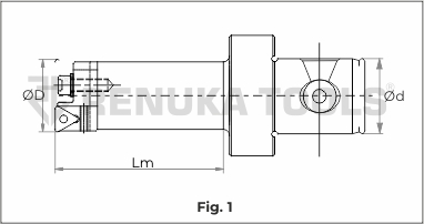
Fig 1 |
1 | RT DUO MT 20‑24 | CART DUO T 20‑24 | NA | 22 | TC..0902 | 20‑24 | 80 | 80 | ST | 0.4 |
|
Fig 2 |
2 | RT DUO MT 24‑30 | CART DUO T 24‑30 | NA | 22 | TC..0902 | 24‑30 | 80 | 80 | ST | 0.5 |
| 3 | RT DUO MT 29‑36 | CART DUO T 29‑36 | NA | 22 | TC..1102 | 29‑36 | 87 | 87 | ST | 0.6 | |
| 4 | RT DUO MT 36‑44 | CART DUO T 36‑44 | NA | 22 | TC..1102 | 36‑44 | 108 | 108 | ST | 1.0 | |
| 5 | RT DUO MT 43‑54 | CART DUO T 43‑54 | EXT DUO 7022/10022 | 22 | TC..1102 | 43‑54 | 115 | 245 | ST | 1.3 | |
| 6 | RT DUO MT 53-66 | CART DUO T 53-66 | EXT DUO 7025/10025 | 25 | TC..1102 | 53-66 | 120 | 260 | ST | 2.0 | |
| 7 | RT DUO MT 65-83 | CART DUO T 65-83 | EXT DUO 7025/10025 | 25 | TC..16T3 | 65-83 | 155 | 295 | ST | 3.8 | |
| 8 | RT DUO MT 82-103 | CART DUO T 82-103 | EXT DUO 7032/10032 | 32 | TC..16T3 | 82-103 | 206 | 356 | ST | 4.6 | |
| 9 | RT DUO MT 100-130 | CART DUO T 100-130 | EXT DUO 7040/10040 | 40 | TC..16T3 | 100-130 | 210 | 370 | ST | 5.5 | |
| 10 | RT DUO MT 125-155 | CART DUO T 125-155 | EXT DUO 7040/10040 | 40 | TC..16T3 | 125-155 | 273 | 433 | AL | 8.5 | |
| 11 | RT DUO MT 150-205 | CART DUO T 150-205 | EXT DUO 7040/10040 | 40 | TC..16T3 | 150-205 | 273 | 433 | AL | 9.0 |
| Sr. No. | Insert | Insert Screw | Torx |
|---|---|---|---|
|
1 |
TC.. 0902 |
M2.2 |
T-6 |
|
2 |
TC..1102 |
M2.5 |
T-7 |
|
3 |
TC..16T3 |
M3.5 |
T-15 |


| Fig. No. | Sr. No | Item Code | Cartridge Item Code | Extension Item Code | Ød | Insert | ØD Range | Lm | Max WL | Flange Mat. | Wt. in KG |
|---|---|---|---|---|---|---|---|---|---|---|---|
|
Fig 1 |
1 | RT DUO MC 20-24 | CART DUO C 20-24 | NA | 22 | CC..0602 | 20-24 | 80 | 80 | ST | 0.4 |
|
Fig 2 |
2 | RT DUO MC 24-30 | CART DUO C 24-30 | NA | 22 | CC..0602 | 24-30 | 80 | 80 | ST | 0.5 |
| 3 | RT DUO MC 29-36 | CART DUO C 29-36 | NA | 22 | CC..0602 | 29-36 | 87 | 87 | ST | 0.6 | |
| 4 | RT DUO MC 36-44 | CART DUO C 36-44 | NA | 22 | CC..0602 | 36-44 | 108 | 108 | ST | 1.0 | |
| 5 | RT DUO MC 43-54 | CART DUO C 43-54 | EXT DUO 7022/10022 | 22 | CC..09T3 | 43-54 | 115 | 245 | ST | 1.3 | |
| 6 | RT DUO MC 53-66 | CART DUO C 53-66 | EXT DUO 7025/10025 | 25 | CC..09T3 | 53-66 | 120 | 260 | ST | 2.0 | |
| 7 | RT DUO MC 65-83 | CART DUO C 65-83 | EXT DUO 7025/10025 | 25 | CC..09T3 | 65-83 | 155 | 295 | ST | 3.8 | |
| 8 | RT DUO MC 82-103 | CART DUO C 82-103 | EXT DUO 7032/10032 | 32 | CC..09T3 | 82-103 | 206 | 356 | ST | 4.6 | |
| 9 | RT DUO MC 100-130 | CART DUO C 100-130 | EXT DUO 7040/10040 | 40 | CC..09T3 | 100-130 | 210 | 370 | ST | 5.5 | |
| 10 | RT DUO MC 125-155 | CART DUO C 125-155 | EXT DUO 7040/10040 | 40 | CC..1204 | 125-155 | 273 | 433 | AL | 8.5 | |
| 11 | RT DUO MC 150‑205 | CART DUO C 150‑205 | EXT DUO 7040/10040 | 40 | CC..1204 | 150‑205 | 273 | 433 | AL | 9.0 |
| Sr. No. | Insert | Insert Screw | Torx |
|---|---|---|---|
|
1 |
CC..0602 |
M2.5 |
T-7 |
|
2 |
CC..09T3 |
M3.5 |
T-15 |
|
3 |
CC..1204 |
M4.5 |
T-20 |
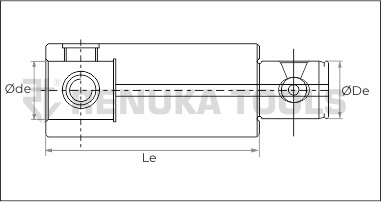

| Sr no. | Item No. | Working Length of Extension (Le) | Øde | ØDe | Wt. in KG |
|---|---|---|---|---|---|
| 1 | EXT DUO 7022 | 70 | 22 | 22 | 0.5 |
| 2 | EXT DUO 10022 | 100 | 22 | 22 | 1.0 |
| 3 | EXT DUO 7025 | 70 | 25 | 25 | 1.1 |
| 4 | EXT DUO 10025 | 100 | 25 | 25 | 1.6 |
| 5 | EXT DUO 7032 | 70 | 32 | 32 | 2.2 |
| 6 | EXT DUO 10032 | 100 | 32 | 32 | 3.0 |
| 7 | EXT DUO 7040 | 70 | 40 | 40 | 2.6 |
| 8 | EXT DUO 10040 | 100 | 40 | 40 | 3.4 |
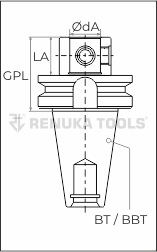


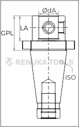

| Sr. No | Item Code | Spindle Taper | Adaptor ID ØdA | LA | GPL of Adaptor | Adaptor Bolt Item Code | Wt. in KG |
|---|---|---|---|---|---|---|---|
| 1 | ADP BT40 22 | BT 40 | 22 | 30 | 57.0 | RTMAB22 | 1.3 |
| 2 | ADP BT40 25 | BT 40 | 25 | 40 | 67.0 | RTMAB25 | 1.6 |
| 3 | ADP BT40 32 | BT 40 | 32 | 50 | 77.0 | RTMAB32 | 2.5 |
| 4 | ADP BT40 40 | BT 40 | 40 | 60 | 87.0 | RTMAB40 | 3.3 |
| 5 | ADP BT50 22 | BT 50 | 22 | 30 | 68.0 | RTMAB22 | 4.0 |
| 6 | ADP BT50 25 | BT 50 | 25 | 40 | 78.0 | RTMAB25 | 4.3 |
| 7 | ADP BT50 32 | BT 50 | 32 | 50 | 88.0 | RTMAB32 | 5.1 |
| 8 | ADP BT50 40 | BT 50 | 40 | 60 | 98.0 | RTMAB40 | 5.4 |
| 9 | ADP HSKA63 22 | HSKA 63 | 22 | 30 | 56.0 | RTMAB22 | 1.1 |
| 10 | ADP HSKA63 25 | HSKA 63 | 25 | 40 | 66.0 | RTMAB25 | 1.2 |
| 11 | ADP HSKA63 32 | HSKA 63 | 32 | 50 | 76.0 | RTMAB32 | 1.7 |
| 12 | ADP HSKA63 40 | HSKA 63 | 40 | 60 | 86.0 | RTMAB40 | 2.0 |
| 13 | ADP BBT40 22 | BBT 40 | 22 | 30 | 57.0 | RTMAB22 | 1.3 |
| 14 | ADP BBT40 25 | BBT 40 | 25 | 40 | 67.0 | RTMAB25 | 1.6 |
| 15 | ADP BBT40 32 | BBT 40 | 32 | 50 | 77.0 | RTMAB32 | 2.5 |
| 16 | ADP BBT40 40 | BBT 40 | 40 | 60 | 87.0 | RTMAB40 | 3.3 |
| 17 | ADP BBT50 22 | BBT 50 | 22 | 30 | 68.0 | RTMAB22 | 4.0 |
| 18 | ADP BBT50 25 | BBT 50 | 25 | 40 | 78.0 | RTMAB25 | 4.3 |
| 19 | ADP BBT50 32 | BBT 50 | 32 | 50 | 88.0 | RTMAB32 | 5.1 |
| 20 | ADP BBT50 40 | BBT 50 | 40 | 60 | 98.0 | RTMAB40 | 5.4 |
| 21 | ADP HSKA100 22 | HSKA 100 | 22 | 30 | 59.0 | RTMAB22 | 2.3 |
| 22 | ADP HSKA100 25 | HSKA 100 | 25 | 40 | 69.0 | RTMAB25 | 2.6 |
| 23 | ADP HSKA100 32 | HSKA 100 | 32 | 50 | 79.0 | RTMAB32 | 3.0 |
| 24 | ADP HSKA100 40 | HSKA 100 | 40 | 60 | 89.0 | RTMAB40 | 3.7 |
| 25 | ADP SK40 22 | SK 40 | 22 | 30 | 49.1 | RTMAB22 | 1.0 |
| 26 | ADP SK40 25 | SK 40 | 25 | 40 | 59.1 | RTMAB25 | 1.2 |
| 27 | ADP SK40 32 | SK 40 | 32 | 50 | 69.1 | RTMAB32 | 1.8 |
| 28 | ADP SK40 40 | SK 40 | 40 | 60 | 79.1 | RTMAB40 | 2.2 |
| 29 | ADP SK50 22 | SK 50 | 22 | 30 | 49.1 | RTMAB22 | 3.0 |
| 30 | ADP SK50 25 | SK 50 | 25 | 40 | 59.1 | RTMAB25 | 3.3 |
| 31 | ADP SK50 32 | SK 50 | 32 | 50 | 69.1 | RTMAB32 | 3.7 |
| 32 | ADP SK50 40 | SK 50 | 40 | 60 | 79.1 | RTMAB40 | 4.0 |
| 33 | ADP HSKA50 22 | HSKA 50 | 22 | 30 | 56.0 | RTMAB22 | 0.6 |
| 34 | ADP HSKA50 25 | HSKA 50 | 25 | 42 | 68.0 | RTMAB25 | 0.9 |
| 35 | ADP HSKA50 32 | HSKA 50 | 32 | 50 | 76.0 | RTMAB32 | 1.2 |
| 36 | ADP HSKA50 40 | HSKA 50 | 40 | 74 | 100.0 | RTMAB40 | 2.0 |
| 37 | ADP ISO40 22 | ISO 40 | 22 | 30 | 41.6 | RTMAB22 | 1.0 |
| 38 | ADP ISO40 25 | ISO 40 | 25 | 40 | 51.6 | RTMAB25 | 1.3 |
| 39 | ADP ISO40 32 | ISO 40 | 32 | 50 | 61.6 | RTMAB32 | 1.8 |
| 40 | ADP ISO40 40 | ISO 40 | 40 | 60 | 71.6 | RTMAB40 | 2.0 |
| 41 | ADP ISO50 22 | ISO 50 | 22 | 30 | 45.2 | RTMAB22 | 3.0 |
| 42 | ADP ISO50 25 | ISO 50 | 25 | 40 | 55.2 | RTMAB25 | 3.3 |
| 43 | ADP ISO50 32 | ISO 50 | 32 | 50 | 65.2 | RTMAB32 | 3.8 |
| 44 | ADP ISO50 40 | ISO 50 | 40 | 60 | 75.2 | RTMAB40 | 4.1 |
| 45 | ADP HSKA80 22 | HSKA 80 | 22 | 30 | 56.0 | RTMAB22 | 1.4 |
| 46 | ADP HSKA80 25 | HSKA 80 | 25 | 40 | 66.0 | RTMAB25 | 1.6 |
| 47 | ADP HSKA80 32 | HSKA 80 | 32 | 50 | 76.0 | RTMAB32 | 2.1 |
| 48 | ADP HSKA80 40 | HSKA 80 | 40 | 60 | 86.0 | RTMAB40 | 2.4 |
| 49 | ADP ISO60 22 | ISO 60 | 22 | 30 | 49.2 | RTMAB22 | 10.8 |
| 50 | ADP ISO60 25 | ISO 60 | 25 | 40 | 59.2 | RTMAB25 | 11.0 |
| 51 | ADP ISO60 32 | ISO 60 | 32 | 50 | 69.2 | RTMAB32 | 11.5 |
| 52 | ADP ISO60 40 | ISO 60 | 40 | 60 | 79.2 | RTMAB40 | 11.8 |