
| Sr. No | Item Code | Insert | Db | L1 | F1 | Dmin | Mounting
Screw |
Insert
Screw |
Torx/Allen key |
Spanner | |
|---|---|---|---|---|---|---|---|---|---|---|---|
| LH | RH | ||||||||||
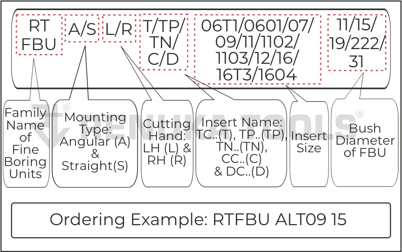
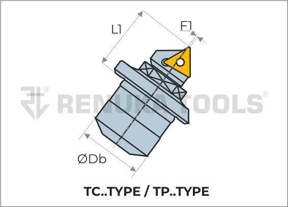
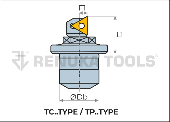
| 1 | RT FBU ALT 06T1 11 | RT FBU ART 06T1 11 | TC..06T1.. | 11.11 | 11.7 | 1.11 | 19 | RTMS11 | M2.0 | T6/1.5MM | RTS11 |
| 2 | RT FBU ALT 0601 11 | RT FBU ART 0601 11 | TC..0601.. | 11.11 | 11.7 | 1.11 | 19 | RTMS11 | M2.0 | T6/1.5MM | RTS11 |
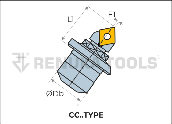
| 3 | RT FBU ALC 06 15 | RT FBU ARC 06 15 | CC..0602.. | 15.08 | 14.0 | 0.46 | 25 | RTMS15 | M2.5 | T8/2.0MM | RTS15 |
| 4 | RT FBU ALT 09 15 | RT FBU ART 09 15 | TC..0902.. | 15.08 | 14.0 | 0.46 | 25 | RTMS15 | M2.2 | T7/2.0MM | RTS15 |
| 5 | RT FBU ALTP 09 15 | RT FBU ARTP 09 15 | TP..0902.. | 15.08 | 14.0 | 0.46 | 25 | RTMS15 | M2.5 | T8/2.0MM | RTS15 |
| 6 | RT FBU ALC 09 19 | RT FBU ARC 09 19 | TC..1102.. | 19.05 | 18.9 | 0.7 | 36 | RTMS19 | M3.5 | T15/2.0MM | RTS19 |
| 7 | RT FBU ALT 1102 19 | RT FBU ART 1102 19 | TC..1102.. | 19.05 | 18.9 | 0.7 | 36 | RTMS19 | M2.5 | T8/2.0MM | RTS19 |
| 8 | RT FBU ALT 1103 19 | RT FBU ART 1103 19 | TC..1103.. | 19.05 | 18.9 | 0.7 | 36 | RTMS19 | M2.5 | T8/2.0MM | RTS19 |
| 9 | RT FBU ALTP 11 19 | RT FBU ARTP 11 19 | TP..1103.. | 19.05 | 18.9 | 0.7 | 36 | RTMS19 | M3.0 | T10/2.0MM | RTS19 |
| 10 | RT FBU ALTN 11 19 | RT FBU ARTN 11 19 | TN..1103.. | 19.05 | 18.9 | 0.7 | 36 | RTMS19 | * | 2.5MM/2.0MM | RTS19 |
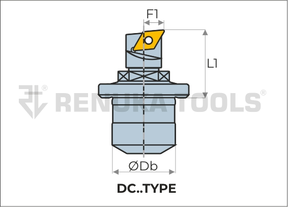
| 11 | RT FBU ALD 07 19 | RT FBU ARD 07 19 | DC..0702.. | 19.05 | 18.9 | 2.3 | 36 | RTMS19 | M2.5 | T8/2.0MM | RTS19 |
| 12 | RT FBU ALC 09 222 | RT FBU ARC 09 222 | CC..09T3.. | 22.225 | 23.15 | 0.8 | 47 | RTMS222 | M3.5 | T15/2.0MM | RTS222 |
| 13 | RT FBU ALT 1102 222 | RT FBU ART 1102 222 | TC..1102.. | 22.225 | 23.15 | 0.54 | 47 | RTMS222 | M2.5 | T8/2MM | RTS222 |
| 14 | RT FBU ALT 1103 222 | RT FBU ART 1103 222 | TC..1103.. | 22.225 | 23.15 | 0.54 | 47 | RTMS222 | M2.5 | T10/2.0MM | RTS222 |
| 15 | RT FBU ALTP 11 222 | RT FBU ARTP 11 222 | TP..1103.. | 22.225 | 23.15 | 0.54 | 47 | RTMS222 | M3.0 | T10/2MM | RTS222 |
| 16 | RT FBU ALTN 11 222 | RT FBU ARTN 11 222 | TN..1103.. | 22.225 | 23.15 | 0.54 | 47 | RTMS222 | * | 2.5MM/2.0MM | RTS222 |
| 17 | RT FBU ALD 07 222 | RT FBU ARD 07 222 | DC..0702.. | 22.225 | 23.15 | 2.3 | 47 | RTMS222 | M2.5 | T8/2.0MM | RTS222 |
| 18 | RT FBU ALC 12 31 | RT FBU ARC 12 31 | CC..1204.. | 31.75 | 34.4 | 0.86 | 73 | RTMS31 | M4.5 | T20/3.0MM | RTS31 |
| 19 | RT FBU ALT 16 31 | RT FBU ART 16 31 | TC..16T3.. | 31.75 | 34.4 | 0.86 | 73 | RTMS31 | M3.5 | T15/3.0MM | RTS31 |
| 20 | RT FBU ALTP 16T3 31 | RT FBU ARTP 16T3 31 | TP..16T3.. | 31.75 | 34.4 | 0.86 | 73 | RTMS31 | M3.5 | T15/3.0MM | RTS31 |
| 21 | RT FBU ALTP 1604 31 | RT FBU ARTP 1604 31 | TP..1604.. | 31.75 | 34.4 | 0.86 | 73 | RTMS31 | M4.0 | T15/3.0MM | RTS31 |
| 22 | RT FBU ALTN 16 31 | RT FBU ARTN 16 31 | TN..1604.. | 31.75 | 34.4 | 0.86 | 73 | RTMS31 | * | 3.5MM/3.0MM | RTS31 |
| Sr. No | Insert | Lever | Lever Screw | Shim | Shim Pin | Allen Key |
|---|---|---|---|---|---|---|
| 1 | TN..1103 | TNL11 | TNLS11 | TNS11 | TNSP11 | 2.5MM |
| 2 | TN..1604 | TNL16 | TNLS16 | TNS16 | TNSP16 | 3.5MM |


| Sr. No | Item Code | Insert | Db | L1 | F1 | Dmin | Mounting
Screw |
Insert
Screw |
Torx/Allen key |
Spanner | |
|---|---|---|---|---|---|---|---|---|---|---|---|
| LH | RH | ||||||||||
| 1 | RT FBU SLT 06T1 11 | RT FBU SRT 06T1 11 | TC..06T1.. | 11.11 | 10.3 | 2.6 | 19 | RTMS11 | M2.0 | T6/1.5MM | RTS11 |
| 2 | RT FBU SLT 0601 11 | RT FBU SRT 0601 11 | TC..0601.. | 11.11 | 10.3 | 2.6 | 19 | RTMS11 | M2.0 | T6/1.5MM | RTS11 |
| 3 | RT FBU SLC 06 15 | RT FBU SRC 06 15 | CC..0602.. | 15.08 | 14 | 3.6 | 25 | RTMS15 | M2.5 | T8/2.0MM | RTS15 |
| 4 | RT FBU SLT 09 15 | RT FBU SRT 09 15 | TC..0902.. | 15.08 | 14.9 | 3.6 | 25 | RTMS15 | M2.2 | T7/2.0MM | RTS15 |
| 5 | RT FBU SLTP 09 15 | RT FBU SRTP 09 15 | TP..0902.. | 15.08 | 14.9 | 3.6 | 25 | RTMS15 | M2.5 | T8/2.0MM | RTS15 |
| 6 | RT FBU SLC 09 19 | RT FBU SRC 09 19 | CC..09T3.. | 19.05 | 14.9 | 4 | 36 | RTMS19 | M3.5 | T15/2.0MM | RTS19 |
| 7 | RT FBU SLT 1102 19 | RT FBU SRT 1102 19 | TC..1102.. | 19.05 | 17.8 | 4 | 36 | RTMS19 | M2.5 | T8/2.0MM | RTS19 |
| 8 | RT FBU SLT 1103 19 | RT FBU SRT 1103 19 | TC..1103.. | 19.05 | 17.8 | 4 | 36 | RTMS19 | M2.5 | T8/2.0MM | RTS19 |
| 9 | RT FBU SLTP 11 19 | RT FBU SRTP 11 19 | TP..1103.. | 19.05 | 17.8 | 4 | 36 | RTMS19 | M3.0 | T10/2.0MM | RTS19 |
| 10 | RT FBU SLTN 11 19 | RT FBU SRTN 11 19 | TN..1103.. | 19.05 | 17.8 | 4 | 36 | RTMS19 | * | 2.5MM/2.0MM | RTS19 |
| 11 | RT FBU SLD 07 19 | RT FBU SRD 07 19 | DC..0702.. | 19.05 | 17.8 | 4 | 36 | RTMS19 | M2.5 | T8/2.0MM | RTS19 |
| 12 | RT FBU SLC 09 222 | RT FBU SRC 09 222 | CC..09T3.. | 22.225 | 21.5 | 4.8 | 47 | RTMS222 | M3.5 | T15/2.0MM | RTS222 |
| 13 | RT FBU SLT 1102 222 | RT FBU SRT 1102 222 | TC..1102.. | 22.225 | 21.5 | 4.8 | 47 | RTMS222 | M2.5 | T8/2MM | RTS222 |
| 14 | RT FBU SLT 1103 222 | RT FBU SRT 1103 222 | TC..1103.. | 22.225 | 21.5 | 4.8 | 47 | RTMS222 | M2.5 | T10/2.0MM | RTS222 |
| 15 | RT FBU SLTP 11 222 | RT FBU ARTP 11 222 | TP..1103.. | 22.225 | 21.5 | 4.8 | 47 | RTMS222 | M3.0 | T10/2MM | RTS222 |
| 16 | RT FBU SLTN 11 222 | RT FBU SRTN 11 222 | TN..1103.. | 22.225 | 21.5 | 4.8 | 47 | RTMS222 | * | 2.5MM/2.0MM | RTS222 |
| 17 | RT FBU SLD 07 222 | RT FBU SRD 07 222 | DC..0702.. | 22.225 | 21.5 | 4.8 | 47 | RTMS222 | M2.5 | T8/2.0MM | RTS222 |
| 18 | RT FBU SLC 12 31 | RT FBU SRC 12 31 | CC..1204.. | 31.75 | 31.4 | 7.1 | 73 | RTMS31 | M4.5 | T20/3.0MM | RTS31 |
| 19 | RT FBU SLT 16 31 | RT FBU SRT 16 31 | TC..16T3.. | 31.75 | 31.4 | 7.1 | 73 | RTMS31 | M3.5 | T15/3.0MM | RTS31 |
| 20 | RT FBU SLTP 16T3 31 | RT FBU SRTP 16T3 31 | TP..16T3.. | 31.75 | 31.4 | 7.1 | 73 | RTMS31 | M3.5 | T15/3.0MM | RTS31 |
| 21 | RT FBU SLTP 1604 31 | RT FBU SRTP 1604 31 | TP..1604.. | 31.75 | 31.4 | 7.1 | 73 | RTMS31 | M4.0 | T15/3.0MM | RTS31 |
| 22 | RT FBU SLTN 16 31 | RT FBU SRTN 16 31 | TN..1604.. | 31.75 | 31.4 | 7.1 | 73 | RTMS31 | * | 3.5MM/3.0MM | RTS31 |
| Sr. No | Insert | Lever | Lever Screw | Shim | Shim Pin | Allen Key |
|---|---|---|---|---|---|---|
| 1 | TN..1103 | TNL11 | TNLS11 | TNS11 | TNSP11 | 2.5MM |
| 2 | TN..1604 | TNL16 | TNLS16 | TNS16 | TNSP16 | 3.5MM |


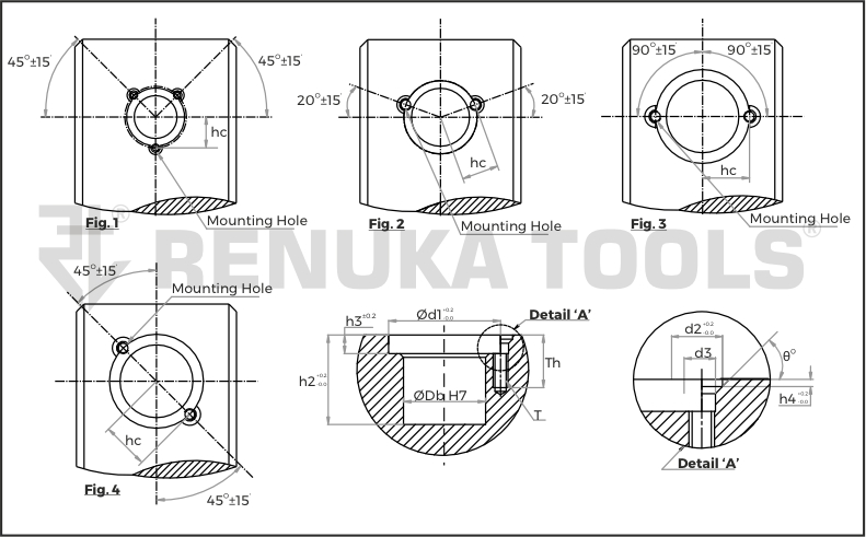
| Fig. | Sr.No | Db H7 | d1 | d2 | d3 | h2 | h3 | h4 | θ° | Th | hc | T |
|---|---|---|---|---|---|---|---|---|---|---|---|---|
| Fig.1 | 1 | 11.11 | 15.06 | 3.5 | 2.4 | 11.1 | 2.7 | 1.58 | 45 | 6 | 8.00±0.02 | M2.0 |
| Fig.2 | 2 | 15.08 | 19.05 | 4.65 | 3.3 | 12.4 | 3.2 | 1.15 | 49 | 8 | 9.58±0.02 | M3.0 |
| Fig.3 | 3 | 19.05 | 24.58 | 5.7 | 3.5 | 18.7 | 4 | 1.3 | 49 | 11 | 12.29±0.05 | M3.0 |
| 4 | 22.225 | 31.75 | 7.2 | 3.8 | 24.8 | 4.8 | 1.1 | 49 | 13 | 15.88±0.05 | M3.5 | |
| 5 | 31.75 | 46.02 | 9.55 | 5.4 | 37.8 | 6.4 | 1.15 | 49 | 17 | 23.01±0.05 | M5.0 |
| Fig. | Sr.No | Db H7 | d1 | d2 | d3 | h2 | h3 | h4 | θ° | Th | hc | T |
|---|---|---|---|---|---|---|---|---|---|---|---|---|
| Fig.4 | 1 | 11.11 | 15.06 | 3.5 | 2.4 | 11.1 | 2.7 | 1.58 | 45 | 6 | 8.00±0.02 | M2.0 |
| 2 | 15.08 | 19.05 | 5.8 | 3.2 | 12.4 | 3.2 | 1.15 | 49 | 8 | 10.30±0.02 | M3.0 | |
| 3 | 19.05 | 24.58 | 5.7 | 3.5 | 18.7 | 4 | 1.3 | 49 | 11 | 12.29±0.05 | M3.0 | |
| 4 | 22.225 | 31.75 | 7.2 | 3.8 | 24.8 | 4.8 | 1.1 | 49 | 13 | 15.88±0.05 | M3.5 | |
| 5 | 31.75 | 46.02 | 9.55 | 5.4 | 37.8 | 6.4 | 1.15 | 49 | 17 | 23.01±0.05 | M5.0 |
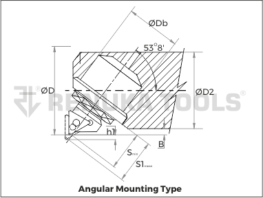
| sr no | Db | RT MBU ITEM CODE | INSERTS | D min | D2 | Bmin | h1max | Smin | S1mean | -ve range (radial) | +ve range (radial) | |
|---|---|---|---|---|---|---|---|---|---|---|---|---|
| LH | RH | |||||||||||
| 1 | 11.11 | RT FBU ALT 06T1 11 | RT FBU ART 06T1 11 | TC..06T104 | 19 | 17 | 0.84 | 1 | 8.6 | 8.8 | 0.16 | 0.84 |
| 2 | 11.11 | RT FBU ALT 0601 11 | RT FBU ART 0601 11 | TC..06T104 | 19 | 17 | 0.84 | 1 | 8.6 | 8.8 | 0.16 | 0.84 |
| 3 | 15.08 | RT FBU ALC 06 15 | RT FBU ARC 06 15 | CC..060204 | 25 | 23 | 0.678 | 1.1 | 11.325 | 11.7 | 0.3 | 0.8 |
| 4 | 15.08 | RT FBU ALT 09 15 | RT FBU ART 09 15 | TC..090204 | 25 | 23 | 0.678 | 1.1 | 11.325 | 11.7 | 0.3 | 0.8 |
| 5 | 15.08 | RT FBU ALTP 09 15 | RT FBU ARTP 09 15 | TP..090204 | 25 | 23 | 0.678 | 1.1 | 11.325 | 11.7 | 0.3 | 0.8 |
| 6 | 19.05 | RT FBU ALC 09 19 | RT FBU ARC 09 19 | CC..09T304; | 36 | 34 | 0.598 | 1.7 | 14.4 | 14.9 | 0.4 | 1.3 |
| 7 | 19.05 | RT FBU ALT 1102 19 | RT FBU ART 1102 19 | TC..110204 | 36 | 34 | 0.598 | 1.7 | 14.4 | 14.9 | 0.4 | 1.3 |
| 8 | 19.05 | RT FBU ALT 1103 19 | RT FBU ART 1103 19 | TC..110304 | 36 | 34 | 0.598 | 1.7 | 14.4 | 14.9 | 0.4 | 1.3 |
| 9 | 19.05 | RT FBU ALTP 11 19 | RT FBU ARTP 11 19 | TP..110304 | 36 | 34 | 0.598 | 1.7 | 14.4 | 14.9 | 0.4 | 1.3 |
| 10 | 19.05 | RT FBU ALTN 11 19 | RT FBU ARTN 11 19 | TN..110304 | 36 | 34 | 0.598 | 1.7 | 14.4 | 14.9 | 0.4 | 1.3 |
| 11 | 19.05 | RT FBU ALD 07 19 | RT FBU ARD 07 19 | DC..070204 | 36 | 34 | 0.598 | 1.7 | 14.4 | 14.9 | 0.4 | 1.3 |
| 12 | 22.225 | RT FBU ALC 09 222 | RT FBU ARC 09 222 | CC..09T304 | 47 | 44 | 1.098 | 2.7 | 17.6 | 18.35 | 0.6 | 2.1 |
| 13 | 22.225 | RT FBU ALT 1102 222 | RT FBU ART 1102 222 | TC..110204 | 47 | 44 | 1.098 | 2.7 | 17.6 | 18.35 | 0.6 | 2.1 |
| 14 | 22.225 | RT FBU ALT 1103 222 | RT FBU ART 1103 222 | TC..110304 | 47 | 44 | 1.098 | 2.7 | 17.6 | 18.35 | 0.6 | 2.1 |
| 15 | 22.225 | RT FBU ALTP 11 222 | RT FBU ARTP 11 222 | TP..110304 | 47 | 44 | 1.098 | 2.7 | 17.6 | 18.35 | 0.6 | 2.1 |
| 16 | 22.225 | RT FBU ALTN 11 222 | RT FBU ARTN 11 222 | TP..110304 | 47 | 44 | 1.098 | 2.7 | 17.6 | 18.35 | 0.6 | 2.1 |
| 17 | 22.225 | RT FBU ALD 07 222 | RT FBU ARD 07 222 | DC..070204 | 47 | 44 | 1.098 | 2.7 | 17.6 | 18.35 | 0.6 | 2.1 |
| 18 | 31.75 | RT FBU ALC 12 31 | RT FBU ARC 12 31 | CC..120404 | 73 | 70 | 0.776 | 4.2 | 27.125 | 28 | 0.7 | 3.5 |
| 19 | 31.75 | RT FBU ALT 16 31 | RT FBU ART 16 31 | TC..16T304 | 73 | 70 | 0.776 | 4.2 | 27.125 | 28 | 0.7 | 3.5 |
| 20 | 31.75 | RT FBU ALTP 16T3 31 | RT FBU ARTP 16T3 31 | TP..16T304 | 73 | 70 | 0.776 | 4.2 | 27.125 | 28 | 0.7 | 3.5 |
| 21 | 31.75 | RT FBU ALTP 1604 31 | RT FBU ARTP 1604 31 | TP..160404 | 73 | 70 | 0.776 | 4.2 | 27.125 | 28 | 0.7 | 3.5 |
| 22 | 31.75 | RT FBU ALTN 16 31 | RT FBU ARTN 16 31 | TN..160404 | 73 | 70 | 0.776 | 4.2 | 27.125 | 28 | 0.7 | 3.5 |

| sr no | Db | RT MBU ITEM CODE | INSERTS | D min | D2 | Bmin | h1max | Smin | S1mean | -ve range (radial) | +ve range (radial) | |
|---|---|---|---|---|---|---|---|---|---|---|---|---|
| LH | RH | |||||||||||
| 1 | 11.11 | RT FBU SLT 06T1 11 | RT FBU SRT 06T1 11 | TC..06T104 | 19 | 17 | 0.8 | 1.2 | 7.2 | 7.4 | 0.2 | 1 |
| 2 | 11.11 | RT FBU SLT 0601 11 | RT FBU SRT 0601 11 | TC..06T104 | 19 | 17 | 0.8 | 1.2 | 7.2 | 7.4 | 0.2 | 1 |
| 3 | 15.08 | RT FBU SLC 06 15 | RT FBU SRC 06 15 | CC..060204 | 25 | 23 | 0.7 | 1.5 | 10.5 | 10.8 | 0.3 | 1.2 |
| 4 | 15.08 | RT FBU SLT 09 15 | RT FBU SRT 09 15 | TC..090204 | 25 | 23 | 0.7 | 1.5 | 10.5 | 10.8 | 0.3 | 1.2 |
| 5 | 15.08 | RT FBU SLTP 09 15 | RT FBU SRTP 09 15 | TP..090204 | 25 | 23 | 0.7 | 1.5 | 10.5 | 10.8 | 0.3 | 1.2 |
| 6 | 19.05 | RT FBU SLC 09 19 | RT FBU SRC 09 19 | CC..09T304; | 36 | 34 | 0.4 | 2.4 | 13.2 | 13.8 | 0.6 | 1.8 |
| 7 | 19.05 | RT FBU SLT 1102 19 | RT FBU SRT 1102 19 | TC..110204 | 36 | 34 | 0.4 | 2.4 | 13.2 | 13.8 | 0.6 | 1.8 |
| 8 | 19.05 | RT FBU SLT 1103 19 | RT FBU SRT 1103 19 | TC..110304 | 36 | 34 | 0.4 | 2.4 | 13.2 | 13.8 | 0.6 | 1.8 |
| 9 | 19.05 | RT FBU SLTP 11 19 | RT FBU SRTP 11 19 | TP..110304 | 36 | 34 | 0.4 | 2.4 | 13.2 | 13.8 | 0.6 | 1.8 |
| 10 | 19.05 | RT FBU SLTN 11 19 | RT FBU SRTN 11 19 | TN..110304 | 36 | 34 | 0.4 | 2.4 | 13.2 | 13.8 | 0.6 | 1.8 |
| 11 | 19.05 | RT FBU SLD 07 19 | RT FBU SRD 07 19 | DC..070204 | 36 | 34 | 0.4 | 2.4 | 13.2 | 13.8 | 0.6 | 1.8 |
| 12 | 22.225 | RT FBU SLC 09 222 | RT FBU SRC 09 222 | CC..09T304 | 47 | 44 | 0.8 | 3.6 | 16 | 16.7 | 0.7 | 2.9 |
| 13 | 22.225 | RT FBU SLT 1102 222 | RT FBU SRT 1102 222 | TC..110204 | 47 | 44 | 0.8 | 3.6 | 16 | 16.7 | 0.7 | 2.9 |
| 14 | 22.225 | RT FBU SLT 1103 222 | RT FBU SRT 1103 222 | TC..110304 | 47 | 44 | 0.8 | 3.6 | 16 | 16.7 | 0.7 | 2.9 |
| 15 | 22.225 | RT FBU SLTP 11 222 | RT FBU SRTP 11 222 | TP..110304 | 47 | 44 | 0.8 | 3.6 | 16 | 16.7 | 0.7 | 2.9 |
| 16 | 22.225 | RT FBU SLTN 11 222 | RT FBU SRTN 11 222 | TP..110304 | 47 | 44 | 0.8 | 3.6 | 16 | 16.7 | 0.7 | 2.9 |
| 17 | 22.225 | RT FBU SLD 07 222 | RT FBU SRD 07 222 | DC..070204 | 47 | 44 | 0.8 | 3.6 | 16 | 16.7 | 0.7 | 2.9 |
| 18 | 31.75 | RT FBU SLC 12 31 | RT FBU SRC 12 31 | CC..120404 | 73 | 70 | 0.5 | 5.6 | 24 | 25 | 1 | 4.6 |
| 19 | 31.75 | RT FBU SLT 16 31 | RT FBU SRT 16 31 | TC..16T304 | 73 | 70 | 0.5 | 5.6 | 24 | 25 | 1 | 4.6 |
| 20 | 31.75 | RT FBU SLTP 16T3 31 | RT FBU SRTP 16T3 31 | TP..16T304 | 73 | 70 | 0.5 | 5.6 | 24 | 25 | 1 | 4.6 |
| 21 | 31.75 | RT FBU SLTP 1604 31 | RT FBU SRTP 1604 31 | TP..160404 | 73 | 70 | 0.5 | 5.6 | 24 | 25 | 1 | 4.6 |
| 22 | 31.75 | RT FBU SLTN 16 31 | RT FBU SRTN 16 31 | TN..160404 | 73 | 70 | 0.5 | 5.6 | 24 | 25 | 1 | 4.6 |